Signal Processing
Silicon drift detector (SDD) chips absorb X-rays and convert each X-ray photon into a charge cloud proportional to the respective energy. Further signal processing provides the determination of the energy of each detected X-ray photon and leads to an energy-dispersive spectrum which allows the qualification and quantification of the measured specimen with respect to the elemental composition.
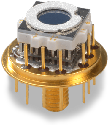

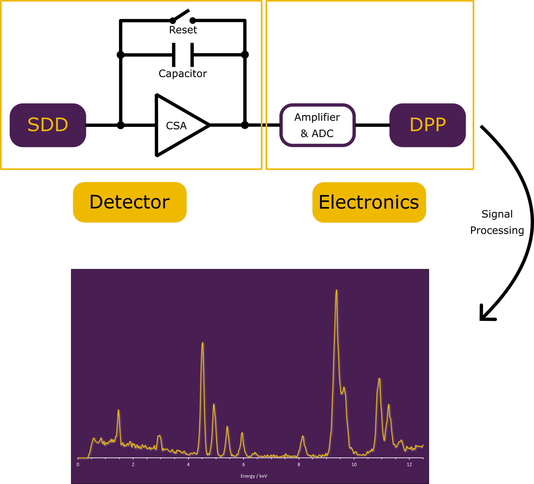
Once an incoming X-ray is absorbed by the SDD, it is converted into a charge cloud and collected at the central anode where it is measured as a potential step (SDD working principle). To generate an energy-dispersive spectrum out of all detected events, each charge cloud must be converted into a voltage step signal and amplified by a charge-sensitive amplifier (CSA). The signal is then further amplified, converted from analog to digital form (ADC), and finally processed by the digital pulse processor (DPP) to determine the energy corresponding to each voltage step respectively detected X-ray. By evaluating all measured events, an energy-dispersive XRF spectrum is produced, enabling the identification and quantification of the elements in the measured sample.
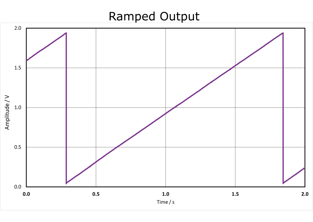
Even in the absence of any X-ray events, the SDD experiences a constant leakage current that flows through the detector, causing a gradual rise in the voltage and generating a steady ramp signal at the CSA output. This leakage current results from the inherent characteristics of the detector. As the potential steadily rises, the ramp signal must be reset once it reaches an upper voltage level before it begins to increase again.
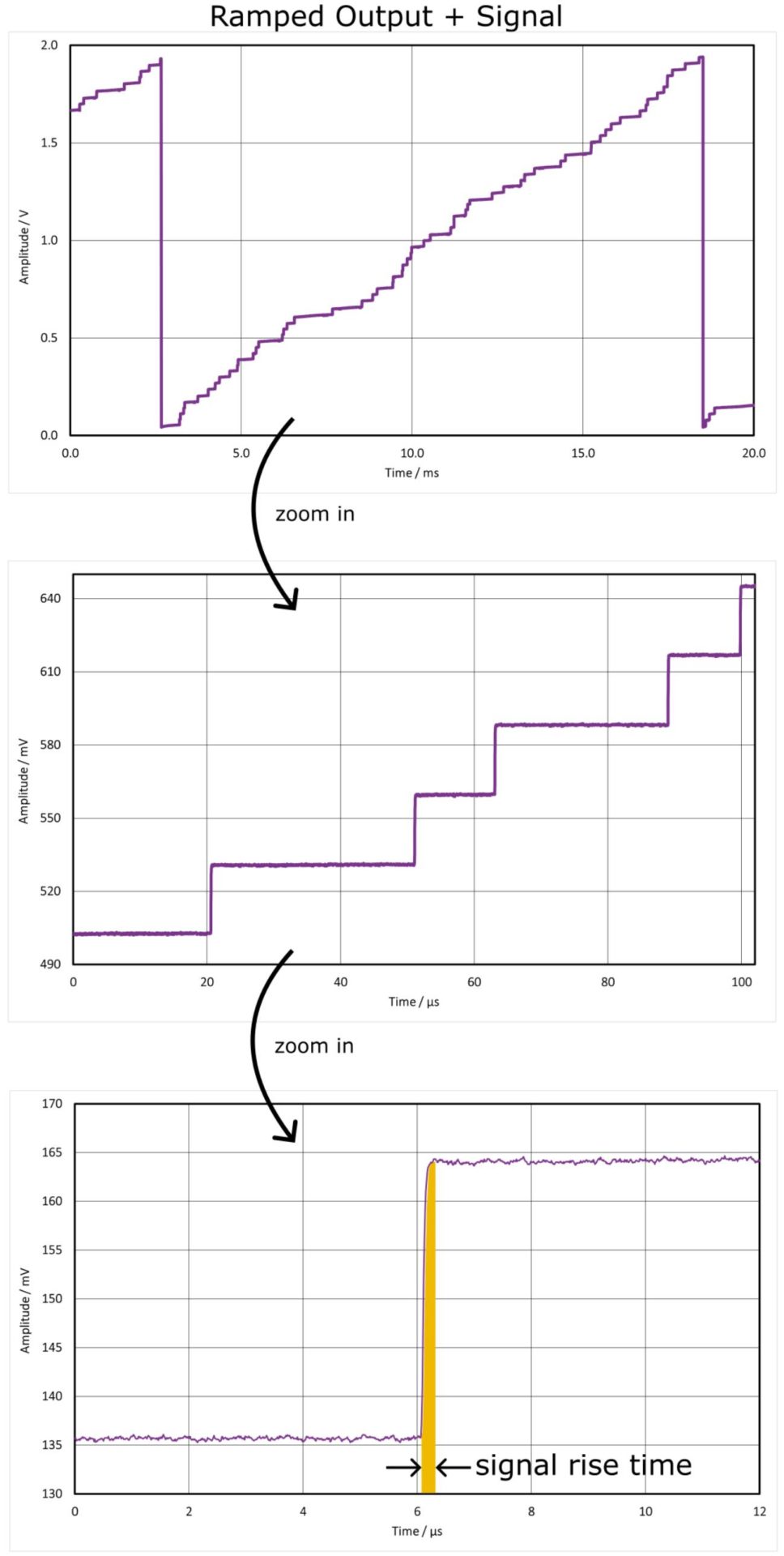
When an X-ray is absorbed by the SDD, it appears as an additional step in the steadily increasing voltage signal. The size of the amplitude of the voltage step depends on the energy of the detected X-ray, or more precisely, on the charge cloud generated by it. The higher the energy of the incoming X-ray, the greater the voltage amplitude in the analog signal output. The time it takes for the voltage to rise during such a step, respectively to collect all electrons of the charge cloud, is called the signal’s rise time. This rise time is influenced not only by the energy of the X-ray photon but also by the lateral distribution of the charge cloud arriving at the SDD anode. A high-quality SDD detector can achieve rise times down to a few tens of nanoseconds. However, this also depends on the size of the detector: for the same X-ray energy absorbed in an outer region far from the central anode, a 7 mm² detector exhibits significantly shorter rise times compared to a 150 mm² detector due to the shorter distance.
When an X-ray is absorbed by the SDD, it appears as an additional step in the steadily increasing voltage signal. The size of the amplitude of the voltage step depends on the energy of the detected X-ray, or more precisely, on the charge cloud generated by it. The higher the energy of the incoming X-ray, the greater the voltage amplitude in the analog signal output. The time it takes for the voltage to rise during such a step , respectively to collect all electrons of the charge cloud, is called the signal’s rise time. This rise time is influenced not only by the energy of the X-ray photon but also by the lateral distribution of the charge cloud arriving at the SDD anode. A high-quality SDD detector can achieve rise times down to a few tens of nanoseconds. However, this also depends on the size of the detector: for the same X-ray energy absorbed in an outer region far from the central anode, a 7 mm² detector exhibits significantly shorter rise times compared to a 150 mm² detector due to the shorter distance.
The amplitude of the step height for each event is determined by a digital pulse processor (DPP) after the analog signal is converted to a digital signal by an analog-to-digital converter (ADC). This process utilizes a digital filter, known as a slow or energy filter, which continuously processes the input signal.
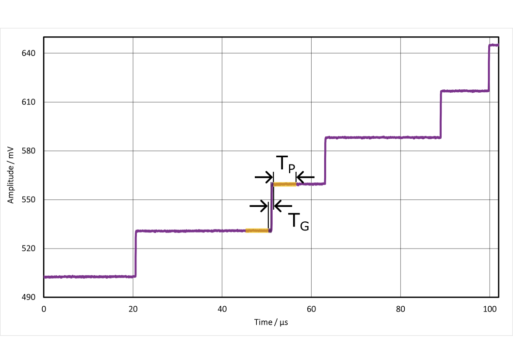
The filter compares the average voltage levels before and after a step, with these regions defined by a specific time period called the peaking time (TP), schematically illustrated as orange areas in the image. These regions are separated by a gap time (TG).
Within each peaking time region, the measured voltages are averaged. The difference between the average values before and after the step determines the step’s amplitude, which is directly proportional to the energy of the detected X-ray photon.
The defined peaking and gap times significantly affect measurement results in terms of energy resolution as well as throughput and should be optimized for each measurement setup.
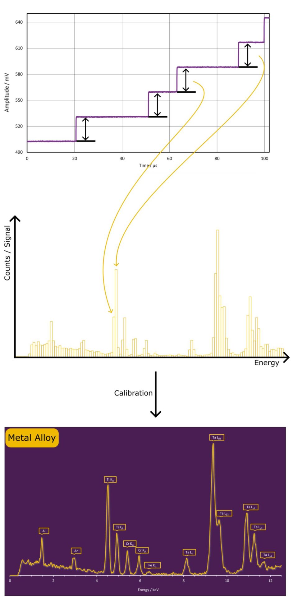
Once the energy of an X-ray event is determined from its voltage step amplitude, the energy is sorted into bins corresponding to specific energy ranges. This process gradually builds an energy-dispersive spectrum, with the number of counted events for each bin. Evidently, using more bins within a fixed energy range improves the resolution of the spectrum but also increases the data size.
To ensure accurate correspondence between the measured and acutal energies, an energy calibration is required. The energy calibration stretches/compresses, and shifts the spectrum as needed to achieve correct energy representation.
In X-ray detection using SDDs, so called “pile-up events” occur when two or more successive X-ray pulses may overlap in the energy filter output. This results in the DPP interpreting the combined signal as a single event with a higher energy, leading to inaccurate energy measurements and false peaks in the spectrum.
To identify pile-up events in the spectrum, a fast filter is used alongside the slow/energy filter. The fast filter also operates with a peaking time (TP) and a gap time (TG), where TP is typically much shorter than the TP of the energy filter, and TG is usually set to zero. Each time the fast filter output exceeds a user-defined trigger threshold an X-ray event is detected. Therefore, the fast filter signals an X-ray event much faster than the slow/energy filter.
To distinguish countable from pile-up events, two key criteria for pile-ups must be met:
- The fast filter must not detect a second event within the pulse processing time conducted by the slow filter.
- The maximum width defines a maximum value for the time, during which the fast filter output is allowed to exceed the trigger threshold.
The image illustrates an example of five simulated X-ray events (A, B, C, D, and E, seen as voltage steps in the blue signal output) and demonstrates how the energy (orange) and fast filter (purple) respond to these events. Each time the fast filter exceeds the threshold value is indicated by a red line. The minimum time interval during which the fast filter must not detect an additional event is represented by a turquoise dotted line. The maximum allowed width for the fast filter is highlighted in light green.
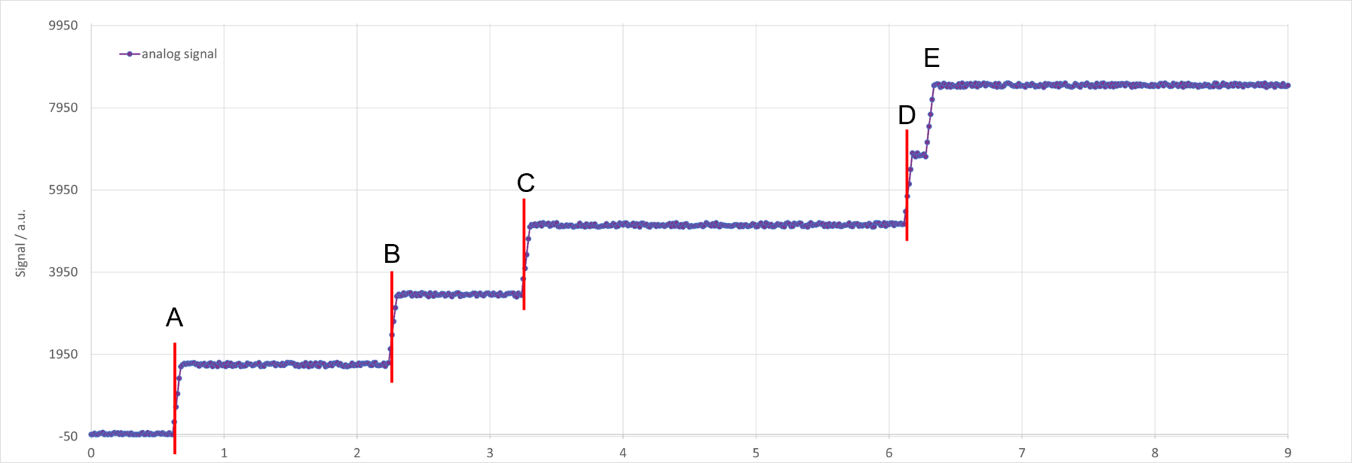
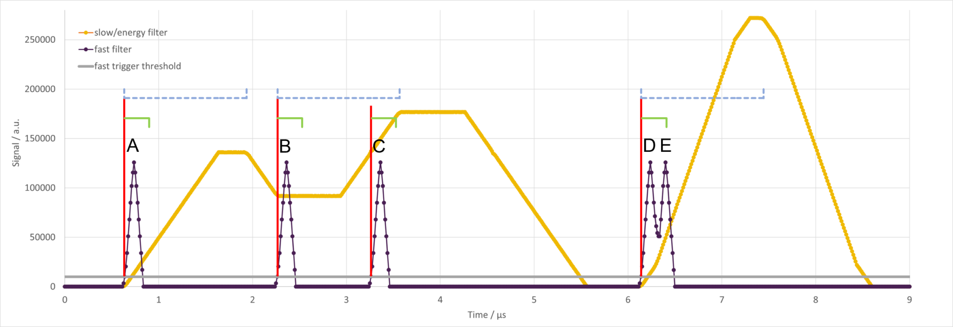
A: The X-ray event triggers the fast filter normally without violating any pile-up criteria. This event is recorded as an input count and can be processed accurately by the energy filter.
B & C: Both events trigger the fast filter, but the time interval between them is too short to determine both X-ray energies correctly with the slow filter and the pile-up criteria a) is violated. As a result both are rejected as pile-up events.
D & E: The fast filter is triggered only once for both events. However, because the duration the fast filter output remains above the trigger threshold exceeds the maximum width criterion, both events are rejected as pile-up.
The more precisely the pile-up criteria are defined, the more effectively pile-up events are rejected. In cases where multiple X-ray events have such a low temporal distance that neither of pile-up criteria is triggered, a pile-up event with wrong energy is sorted into the spectrum.


